Metrobus Fares
Metrobus fare for regular routes is $2.00 using a SmarTrip® card or cash. The fare for express routes is $4.25 using a SmarTrip® card or cash. Fare for seniors and people with disabilities is $1.00 for regular routes, $2.10 on express routes. You must have exact change.Using these voltages, the bus currents are calculated using Eq. (10.25) or (10.26). where yi is the total shunt admittance at the bus i and yiivi is the shunt current flowing from bus i to ground. where VR is the (n−1)×1-dimensional reference voltage vector containing in each element the slack bus voltage.
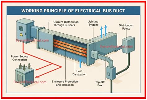
Bus voltage is the voltage on a Bus bar. Bus bars are rigid copper bars (mostly) into which all the generated current (generated from multiple alternators in AC system or from rectifiers in DC system ) is fed and through which it is then distributed or further processed.
The dc bus capacitor is the most important passive component in a traction motor drive. Conventional designs have been using a set of electrolytic bulk capacitors to smooth dc bus voltage.
In general, a DC drive converts an Alternating Current (AC) into Direct Current (DC) to run a DC motor. Most DC drives use a couple of thyristors (also known as SCR's) to create a half cycle of DC output from a single phase AC input (known as half bridge method).
The DC Bus is the voltage required by the inverter to operate and dictates the number of batteries in series required to drive the inverter. This information is available from the UPS supplier and should be clearly indicated in their spec sheets. DC busses range from 12V (1 x battery) to 480V (40 x batteries).
Step 1: Measure dc bus voltage
The dc bus voltage is relative to the peak voltage of the mains input. What to look for: dc bus voltage is ~1.414 x the rms line voltage (e.g., for a 480V ac drive, the dc bus should be ~678V dc. A dc voltage value that is too low can cause the drive to trip.A variable-frequency drive (VFD) transforms the input mains of constant voltage and frequency into a voltage and frequency range that can be varied to control motor torque. The input diodes provide constant dc buffer for the switching inverter section, equivalent to 1.414 times the peak of the input voltage.
Frequent starting, braking and reversing. The disadvantage of D.C. drives is the presence of a mechanical commutator which limits the maximum power rating and the speed. The variable speed applications are dominated by D.C. drives because of lower cost, reliability ad simple control.
DC drive is basically a DC motor speed control system that supplies the voltage to the motor to operate at desired speed. Earlier, the variable DC voltage for the speed control of an industrial DC motor was generated by a DC generator.
The “AC” stands for alternating current. AC-type drives are also known as adjustable speed drives, adjustable frequency drives, and variable speed drives. In contrast, DC drives are used to convert alternating current into direct current (The “DC” in DC drives is an acronym for direct current).
Most DC motors have an armature resistance in the 10s of ohms or less. Measure the motor resistance right at the drive. If the measurement shows an open (high ohm value), the problem is not the drive. Check motor relays, plugs, connectors, conduit boxes, etc.
DC drives are DC motor speed control systems. Since the speed of a DC motor is directly proportional to armature voltage and inversely proportional to motor flux (which is a function of field current), either armature voltage or field current can be used to control speed.
Thus, the speed of a DC motor can be controlled in three ways:
- By varying the supply voltage.
- By varying the flux, and by varying the current through field winding.
- By varying the armature voltage, and by varying the armature resistance.
The various applications of DC shunt motor are in Lathe Machines, Centrifugal Pumps, Fans, Blowers, Conveyors, Lifts, Weaving Machine, Spinning machines, etc. The compound motors are used where higher starting torque and fairly constant speed is required.
The typical VFD for an industrial ac motor typically operates by first rectifying the line voltage (often 440 V three-phase for industrial applications). The resulting dc power travels via the dc bus to an inverter. The inverter generates a pulse-width-modulated waveform.
AC induction motors use a series of coils powered and controlled by AC input voltage. Consequently, AC motors are less efficient than DC motors. In fact, the DC motor is 30% more efficient than AC motors due to the secondary magnetic field being generated from the permanent magnets rather than copper windings.
A DC (direct current) power supply converts electrical energy in the form delivered by the power company to a form required by some device. To maintain a 5 Volt output (referred to as 5 Volts regulated) the internal resistance of the power supply must change depending on the current load.
Possible causes:
- The Input voltage is too high.
- Improper floating ground or high input voltage on one of the phases.
- There are power spikes or surges at the input.
- The drive is going into regeneration (regen).
- Rapid load change is causing a large spike in the DC Bus.
VFDs are designed to roughly track this line, although there may be a voltage boost at low frequencies to get things going. Above the nominal point the voltage is held constant when the frequency is increased, to produce what is called “field weakening”, a necessary precaution to It should also be reduced.
The most common type of VFD control is a scalar method referred to as volts per hertz (V/Hz) or volts per frequency (V/f). A variable frequency drive (VFD) is used to control the speed of AC motors, and does so by varying the frequency of the supply voltage to the motor.
A Variable Frequency Drive (VFD) is a type of motor controller that drives an electric motor by varying the frequency and voltage supplied to the electric motor. Other names for a VFD are variable speed drive, adjustable speed drive, adjustable frequency drive, AC drive, microdrive, and inverter.
VFDs manipulate the frequency of their output by rectifying an incoming AC current into DC, and then using voltage pulse-width modulation to recreate an AC current and voltage output waveform.
An inverter increases the DC voltage, and then changes it to alternating current before sending it out to power a device. Ironically, if you use an AC inverter to power a computer or television, the power supply in the device is converting the 120-volt alternating current into a much lower voltage direct current.
Variable speed AC drives will maintain a constant volts/hertz relationship from 0 - 60 Hertz. For a 460 motor this ratio is 7.6 volts/Hz. To calculate this ratio divide the motor voltage by 60 Hz. At low frequencies the volt- age will be low, as the frequency increases the voltage will increase.
There is no direct relationship between Voltage and frequency. Any voltage like 110 V,220, 400 V can be generated at one frequency e.g 50 Hz , or any other frequencies.
AC Motor. If the demands of the load are too great, the motor starts to draw excessive currents from the VFD. Eventually the current demands become too large for the VFD to handle, so it trips out on an overcurrent fault. Overcurrent faults are the most common faults that will shut down a drive.
The most common time a VFD overvoltage fault occurs is during deceleration. Sometimes the braking torque requirement exceeds drive braking circuit capacity. Other times the deceleration is too fast for its load and inertia from the load is going faster than the designated frequency.
Normally the dc bus voltage in a VFD is 1.414 times the ac RMS line voltage. So for a 480-V unit we're looking at 678 V on the dc bus, requiring the high-voltage differential probe set. In a future article we'll look at diagnostic procedures for a typical VFD.
A VFD overvoltage fault is fairly common with VFD regular usage. A VFD overvoltage fault can occur on power up, during deceleration, acceleration, during normal run, or while sitting idle. If the VFD overvoltage fault occurs during power up, the first thing to check is the incoming line voltage with a meter.
Normally the dc bus voltage in a VFD is 1.414 times the ac RMS line voltage. So for a 480-V unit we're looking at 678 V on the dc bus, requiring the high-voltage differential probe set.